
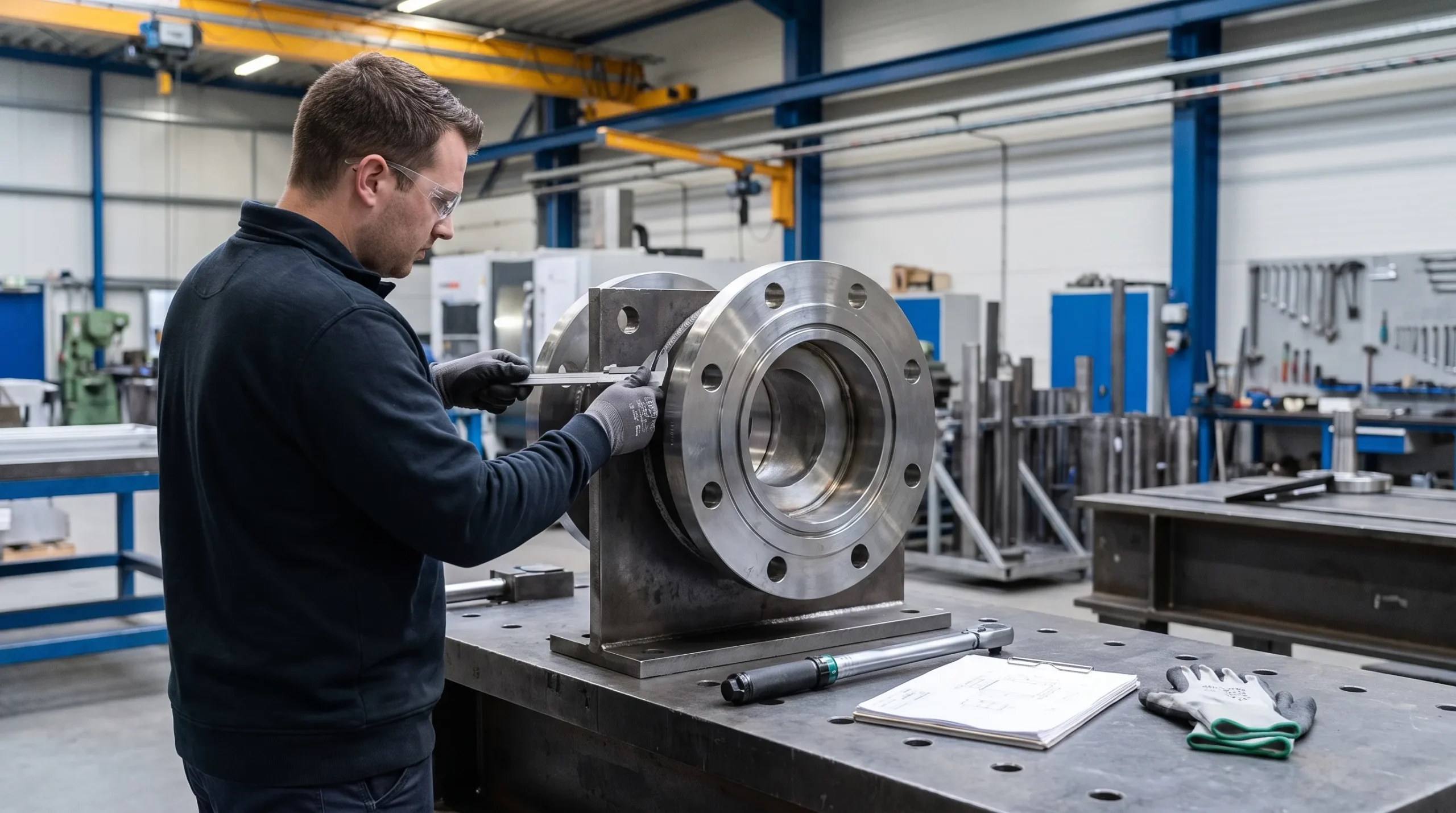
Flanges look simple. In many lifting tools, they appear to be just a plate with a bolt circle, a welded connection, or an adapter between two assemblies. In practice, a flange can determine whether a lifting tool transfers load predictably, keeps alignment under stress, and remains inspectable throughout its service life.
That is why flange design mistakes deserve attention early in engineering, not only during final verification. A lifting tool may have a strong frame, certified hoist points, and a robust operating procedure, but a weak or poorly detailed flange interface can still introduce bending, prying, bolt overload, fatigue cracks, or unsafe handling behavior.
For OEMs, machine builders, high-tech manufacturers, semiconductor equipment suppliers, aerospace companies, and industrial maintenance teams, the practical question is not whether the flange looks strong. The question is whether the complete load path has been engineered, manufactured, documented, inspected, and maintained for the real lifting task.
Why flange design matters in lifting tools
A flange in a lifting tool is rarely an isolated part. It may connect a lifting eye to a spreader beam, attach an adapter to a machine module, support a rotating interface, or connect a custom handling tool to a sensitive product. In all cases, the flange transfers forces from one component to another.
Those forces are not limited to the nominal weight of the load. Lifting tools often experience eccentric loading, angular pulling, dynamic effects during movement, local contact forces, operator-induced misalignment, and repeated loading cycles. If the flange is designed as a static connection for a perfectly vertical load, the real operating conditions may exceed the assumptions behind the design.
The starting point should be the lifting task. What is being lifted, where is the center of gravity, how is the tool connected, what route is used, how much clearance is available, and what happens if the load rotates slightly? These questions are part of sound engineering, and they align with the broader principle that a lifting task must be defined before the lifting plan can be reliable.
A flange is safe only within a defined context. Change the load, orientation, bolts, contact surfaces, or operating method, and the original design assumptions may no longer apply.
Mistake 1: designing only for vertical load
One of the most common flange design mistakes is calculating the interface for the vertical weight of the load while ignoring the moments and side loads created by real use. This is especially risky when the lifting point is offset from the center of gravity or when the tool is used in tight spaces where the hoist line cannot remain perfectly vertical.
A flange that looks adequate under pure tension may behave very differently when bending is introduced. The bolt group may see uneven tension. One side of the flange may lift slightly. Holes may begin to ovalize. A welded flange may develop high local stress near the weld toe. Over time, repeated use can turn a small design margin problem into a fatigue issue.
The engineering check should include combined loading. That means assessing shear, tension, bending, bearing pressure, prying action, contact pressure, and stiffness. For frequently used tools, fatigue and wear should also be considered. A tool that is lifted once for installation has a different risk profile from a production tool used every shift.
Mistake 2: underestimating prying action
Prying action occurs when a flexible flange plate bends and amplifies the tensile load in the bolts. This is a typical risk in bolted flange connections where the bolts are located away from the actual line of force or where the flange is too thin relative to the applied moment.
The problem is that larger bolts do not automatically solve prying. If the flange plate remains too flexible, the connection can still concentrate load in unexpected ways. Bolt preload can reduce slip and improve joint behavior, but it cannot compensate for an interface geometry that allows excessive bending.
Good flange design considers stiffness, bolt location, washer support, thread engagement, surface contact, bolt grade, preload method, and the thickness of both connected parts. In lifting tools, the goal is not simply to keep the parts attached. The goal is to maintain a predictable load path with enough stiffness and integrity for the intended use.
Mistake 3: treating the bolt circle as a layout detail
Bolt pattern design is often underestimated because it appears to be a drafting task. In reality, bolt spacing, edge distance, hole tolerance, access for tightening, and the relationship between bolt positions and load direction can strongly influence safety and maintainability.
If bolts are too close to the edge, the flange can suffer local tearing or deformation. If the bolt circle is too small, the connection may have limited resistance to moment loads. If holes are oversized or slotted without a controlled reason, the joint may shift before the bolts engage in bearing. If technicians cannot reach the bolts with calibrated tools, the intended preload may never be achieved in practice.
This is where design for assembly and design for inspection meet. A flange that cannot be tightened correctly, visually checked, or maintained without removing unrelated equipment creates lifecycle risk, even if the calculation looks acceptable.
| Flange design mistake | Possible field symptom | Risk in lifting use | Practical engineering response |
|---|---|---|---|
| Vertical load only in the calculation | One side of the flange shows lifting or fretting marks | Uneven bolt loading and loss of predictable load path | Include moments, side loads, eccentricity, and dynamic effects |
| Thin flange plate around tensile bolts | Bolts loosen or show high local load marks | Prying action increases bolt tension | Increase joint stiffness and verify prying behavior |
| Poor bolt pattern or edge distance | Deformed holes or local cracking | Reduced resistance to shear or tearing | Review bolt circle, edge margins, bearing pressure, and access |
| Welded flange with abrupt transitions | Cracks near weld toe or heat-affected zone | Fatigue initiation under repeated lifting cycles | Use suitable transitions, weld details, inspection access, and verification |
| Inaccessible bolts or hidden surfaces | Inconsistent tightening and limited inspection evidence | Maintenance quality depends on assumptions | Design for tool access, visual inspection, and measurable checks |
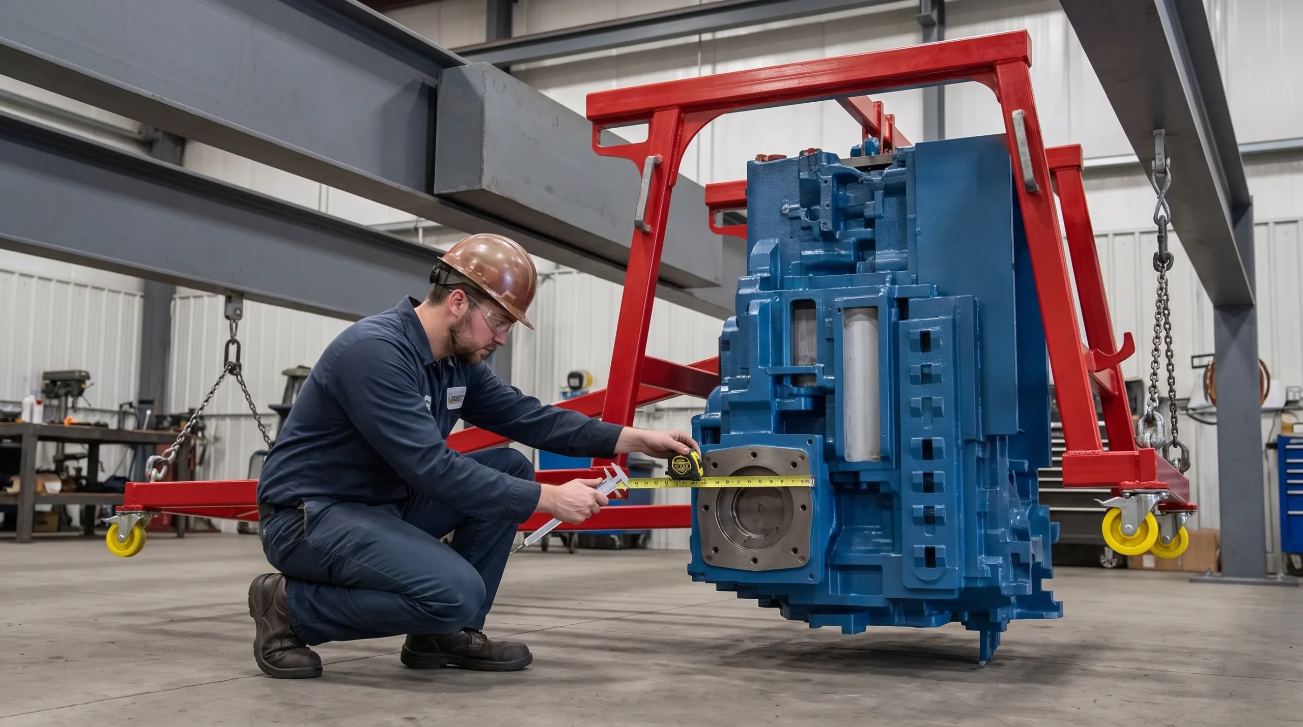
Mistake 4: ignoring weld transitions and local stiffness changes
Many lifting tool flanges are welded to arms, frames, adapter plates, or support structures. The weld itself is important, but the geometry around the weld can be just as critical. Abrupt changes in stiffness, sharp corners, undersized radii, and poor weld access can all concentrate stress.
A flange welded to a thick plate may transfer load into a thinner frame member. A rigid adapter may create local bending in a tube or bracket. A weld that is strong in static loading may still be vulnerable if the tool is used repeatedly and the stress concentration is high.
Good design does not treat the weld as a final line on the drawing. It considers how forces enter and leave the flange, whether load is distributed through the structure, how welding affects distortion and fit-up, and whether the final weld can be inspected. For safety-critical lifting tools, manufacturing feasibility and inspection strategy should be part of the design review, not a separate concern after release.
Mistake 5: overlooking surface contact, flatness and alignment
Bolted flange connections rely on contact. If surfaces are not flat, if coatings are uneven, or if parts do not align correctly, the bolts may be forced to pull components into position. This can add unintended stresses before the lifting tool is even used.
Misalignment can also make the operator's job harder. If the flange interface is difficult to connect, technicians may use force, temporary supports, or non-standard assembly methods. That can damage the tool, compromise bolt preload, or increase exposure to pinch points and suspended-load hazards.
Flatness, parallelism, dowel placement, locating features, and controlled tolerances all matter. In high-tech and semiconductor environments, surface finish, cleanliness, and particle control may also influence the design. In aerospace and industrial maintenance environments, corrosion protection and ruggedness may be more prominent concerns. The same principle applies in all cases: the flange must suit the actual operating environment.
Mistake 6: selecting materials and coatings without considering the joint
Material selection for a flange is not only about tensile strength. Engineers also need to consider toughness, weldability, corrosion behavior, surface hardness, wear, fatigue resistance, and compatibility with bolts and adjacent components.
Coatings deserve similar attention. A coating can change friction conditions under bolt heads, affect torque-to-preload relationships, hide early signs of cracking, or reduce the accuracy of visual inspection. In some environments, corrosion under a coating can become a hidden risk. In others, the coating may be necessary to protect the flange from contamination, humidity, or chemical exposure.
The right answer depends on the application. A lifting tool used inside a clean production area does not face the same conditions as a tool used in outdoor logistics, aviation ground support, or heavy industrial maintenance. Material and coating choices should be recorded in the technical documentation so future maintenance teams understand what may and may not be changed.
Mistake 7: making inspection difficult or ambiguous
A flange may be strong when new, but lifting tools need to remain safe in use. Inspection access is therefore a design requirement. If inspectors cannot see critical welds, check deformation, identify bolt markings, measure wear, or verify whether parts have shifted, the organization has less evidence to support continued use.
Well-designed flange interfaces make inspection practical. Critical areas are visible. Reference surfaces are accessible. Bolts can be checked. Wear marks can be interpreted. If overload testing or periodic examination is required, the tool geometry supports that process rather than obstructing it.
Evidence matters. The same evidence-first mindset is not limited to industrial lifting. In another maintenance context, TapTech describes diagnostic evidence before recommendations for drain work, using inspection so asset condition drives the next step rather than assumptions. Lifting tool inspections benefit from the same discipline: decisions should be based on what the tool shows, what the documentation states, and how the tool has actually been used.
This is also why periodic checks should not be reduced to a tick-box exercise. Visual inspection, dimensional checks, overload testing where appropriate, examination records, and usage advice all help build a clearer picture of tool condition. For more on early warning signs, BKL has explained how safety inspections can reveal issues before failures escalate.
Mistake 8: separating flange design from risk assessment and documentation
In lifting tools, a flange is part of the safety concept. It should be reflected in the risk assessment, design calculations, drawings, inspection criteria, operating instructions, maintenance planning, and technical file where applicable.
For equipment within the scope of European machinery legislation, CE-related work is not only about a mark on the product. It requires a structured conformity approach, risk reduction, and technical evidence. Flange design details may be relevant when demonstrating how load-bearing parts, fastening methods, foreseeable misuse, maintenance access, and inspection requirements have been addressed.
This does not mean every flange must be complex or custom. Some applications can use standard interfaces or proven components when they fit the load case and environment. The risk appears when a standard-looking flange is used in a non-standard lifting situation without verifying the complete system.
This is why occupational safety should be considered during engineering, manufacturing, operation, inspection, and service. BKL's perspective on occupational safety in machine and tooling design follows the same logic: safety is not a final check, it is a design and lifecycle requirement.
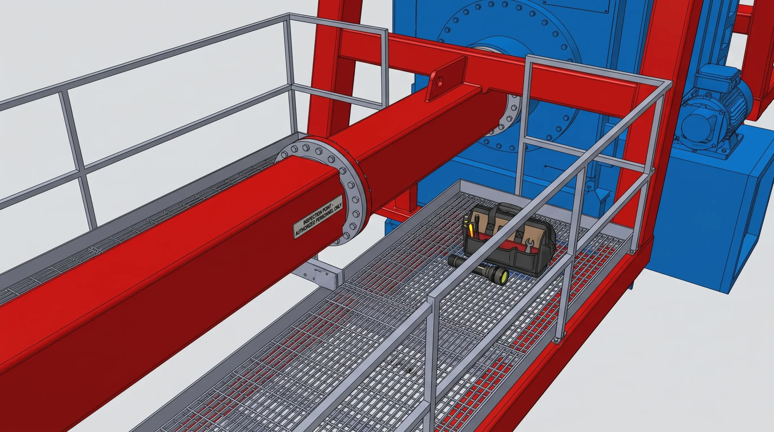
Practical controls that reduce flange-related lifting risk
A good flange design process combines calculation, practical engineering, manufacturing knowledge, inspection planning, and operator feedback. The following controls help reduce risk without making the design unnecessarily complicated.
- Define the lifting task, including load mass, center of gravity, pick-up points, orientation, route, clearance, frequency of use, and foreseeable misuse.
- Verify the full load path from the hoist connection through the flange, bolts, welds, frame, adapters, and contact points on the lifted product.
- Assess combined loads, including shear, tension, bending, prying, bearing pressure, side loading, dynamic movement, fatigue, and local deformation.
- Design bolt connections for real assembly conditions, including access, preload method, thread engagement, locking method, replacement rules, and bolt traceability where needed.
- Control fit-up through tolerances, flatness, locating features, surface preparation, and coating specifications that support predictable joint behavior.
- Make inspection practical by keeping critical surfaces visible, defining acceptance criteria, and documenting what must be checked during periodic inspections.
- Record engineering assumptions, calculations, test reports, manuals, inspection intervals, and usage advice so future teams understand the design limits.
These controls are not only technical. They also support business continuity. A flange failure, cracked weld, damaged bolt pattern, or unclear inspection finding can interrupt production, delay maintenance, or create uncertainty around whether a lifting tool may remain in service.
When an existing flange interface should be reassessed
Existing lifting tools deserve extra attention when the use case has changed or when the tool shows early signs of distress. A tool can appear functional while still carrying hidden risk in the flange interface.
| Trigger for reassessment | Why it matters |
|---|---|
| The lifted product, weight, or center of gravity has changed | Original calculations may no longer match the load case |
| Operators report difficult alignment or forced assembly | Misalignment can introduce preload loss, deformation, or unsafe handling |
| Bolts have been replaced without engineering review | Grade, coating, length, thread engagement, and preload behavior may change |
| Coating cracks, fretting marks, or corrosion appear near the flange | These can indicate movement, overload, moisture ingress, or stress concentration |
| A tool has been overloaded, dropped, modified, or repaired | The original safety assumptions may no longer be valid |
| Documentation is missing or unclear | Inspection and safe use depend on traceable design limits and criteria |
In these situations, waiting for the next planned interval may not be the best decision. A targeted engineering review or inspection can clarify whether the tool can remain in use, needs repair, requires load testing, or should be redesigned.
How BKL supports safer flange and lifting tool decisions
BKL supports companies that need safe, reliable, and user-friendly lifting and handling tools, industrial modules, and machines. That support can include concept development, mechanical and mechatronic engineering, manufacturing, inspections, documentation, maintenance advice, and lifecycle services.
For flange-related risks, the value lies in connecting the disciplines. A calculation is stronger when it reflects the real lifting task. A drawing is stronger when manufacturing and inspection access have been considered. An inspection report is more useful when it links findings to practical usage advice. A repair or redesign decision is more reliable when the tool's history, documentation, and operating environment are understood.
BKL can support partial process steps or complete solutions, depending on what the client needs. For inspection activities, BKL is accredited according to ISO 17020:2012. For engineering and production challenges, the team combines practical mechanical knowledge with experience in high-tech, semicon, optical, aerospace, and industrial environments.
The main goal is not to make every flange heavier or every tool custom. The goal is to make the lifting tool suitable for its task, clear for operators, practical to inspect, and supported by documentation that helps teams use and maintain it responsibly.
FAQ's about flange design mistakes in lifting tools:
Why can a flange become a weak point in a lifting tool? A flange can become a weak point when the real load path is more complex than the design assumptions. Eccentric loading, bending, side loads, prying action, poor bolt layout, weld stress concentrations, or limited inspection access can all increase risk.
Is a thicker flange always safer? Not necessarily. Thickness can improve stiffness, but safe flange design also depends on geometry, bolt pattern, material, weld details, contact surfaces, tolerances, accessibility, and the actual lifting task. A thicker flange with poor load introduction or inaccessible bolts can still create problems.
What are early warning signs of flange problems? Warning signs can include loose bolts, fretting marks, cracked coating, corrosion near joints, deformed holes, visible bending, weld cracks, difficult assembly, unusual movement during lifting, or missing documentation about previous repairs or modifications.
Should existing lifting tools be reviewed if only the bolts are changed? Yes, bolt replacement can affect the connection. Grade, length, coating, washer type, thread engagement, preload method, and locking method can all influence joint behavior. Changes should be checked against the original design assumptions or reviewed by a competent technical specialist.
How does flange design relate to CE documentation? For equipment that falls under applicable machinery legislation, flange design may be part of the technical evidence for load-bearing integrity, risk reduction, maintenance requirements, and safe use instructions. It should be traceable through drawings, calculations, tests, inspection criteria, and manuals where relevant.
When should BKL be involved in a flange-related lifting tool issue? BKL can be involved when a new lifting tool requires engineering, when an existing tool shows wear or damage, when documentation is unclear, when a lifting task has changed, or when a company needs support with design, manufacturing, inspection, repair, or lifecycle planning.
If a flange interface in your lifting tool is difficult to verify, inspect, assemble, or justify with documentation, it is worth reviewing before it becomes an operational issue. BKL can help assess the lifting task, engineer practical improvements, manufacture suitable components, perform inspections, and support lifecycle decisions for safety-critical tools and machines.